September 8, 1892
HOISTING MACHINERY AND SAFETY CLUTCHES;
OTIS ELEVATING CABLE RAILWAY. (With inset.)
 In our issue of Aug.
18 we gave a general description of the construction and equipment
of the Otis Elevating Cable Railway, up the eastern slope of the Catskill
Mountains, and called attention to some of the peculiarities of its
design. We show in the accompanying cuts and on our inset sheet this
week some general photographic views of the incline and complete details
of the hoisting machinery and safety devices,
In our issue of Aug.
18 we gave a general description of the construction and equipment
of the Otis Elevating Cable Railway, up the eastern slope of the Catskill
Mountains, and called attention to some of the peculiarities of its
design. We show in the accompanying cuts and on our inset sheet this
week some general photographic views of the incline and complete details
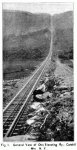
of the hoisting machinery and safety devices,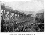 which are used in its operation. It will be remembered that the incline
is 7,000 ft. long along the grade and has a rise of 1,630 ft., with
a maximum grade of 34%. Fig. 1
gives a general view of the line from a point near its bottom and shows
very clearly the construction of that portion of the track laid with
ballast in the ordinary manner. In Fig. 2
is shown a portion of the long trestle, detail drawings of which were
given in the previous article.
which are used in its operation. It will be remembered that the incline
is 7,000 ft. long along the grade and has a rise of 1,630 ft., with
a maximum grade of 34%. Fig. 1
gives a general view of the line from a point near its bottom and shows
very clearly the construction of that portion of the track laid with
ballast in the ordinary manner. In Fig. 2
is shown a portion of the long trestle, detail drawings of which were
given in the previous article.
With regard to the hoisting machinery there is little
to be said in addition to the description given in the first article
which is not plainly shown by the 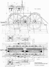 drawings.
In general it does not vary materially from that in use on other cable
inclines except, perhaps, in its magnitude and the unusual precautions
taken to insure safety in operating the road. It is located at the top
of the incline and consists in brief of two Hamilton-Corliss, reversing
engines, with 12 x 30 in. cylinders, driving a single shaft which is
geared to two spur wheels operating the drum shaft and winding drums.
The foundation is of brick and stone masonry on solid rock. The winding
drums are 12 ft. in diameter and are provided with six grooves for the
cables and also with seats for friction brakes, which are to be connected
with a suitable mechanism for throwing them into operation should the
car overrun its proper position at the station. In addition to the brakes
on the drums there are also friction brakes on the engine shaft which
an operated by one of the levers in the operating tower. drawings.
In general it does not vary materially from that in use on other cable
inclines except, perhaps, in its magnitude and the unusual precautions
taken to insure safety in operating the road. It is located at the top
of the incline and consists in brief of two Hamilton-Corliss, reversing
engines, with 12 x 30 in. cylinders, driving a single shaft which is
geared to two spur wheels operating the drum shaft and winding drums.
The foundation is of brick and stone masonry on solid rock. The winding
drums are 12 ft. in diameter and are provided with six grooves for the
cables and also with seats for friction brakes, which are to be connected
with a suitable mechanism for throwing them into operation should the
car overrun its proper position at the station. In addition to the brakes
on the drums there are also friction brakes on the engine shaft which
an operated by one of the levers in the operating tower.
As noted in the previous article, the machinery is
operated from a tower directly above and from which a clear view of
the whole line is had. This is accomplished by three systems of levers
operating the steam and reversing valves and the friction brakes on
the engine shaft.
It will be seen that with the exception of the automatic
stop the operating of the safety devices connected with the hoisting
machinery is in the hands of the operator. To provide against accident,
should the operator become careless, or incapacitated for any cause,
or should the hauling cables break or stretch, safety clutches are attached
to each passenger car. These clutches are designed to work either when
one cable breaks or stretches unduly or when the car exceeds a certain
fixed rate of speed. Details of the clutches are shown in Figs.
7 & 11,  on
the inset sheet. They were designed by Mr. Thos. E. Brown, Jr., M. Am.
Soc. C. E. (to whom we are indebted for the blue prints, from which
our drawings are made), and are used for the first time on this line.
The operation of the clutches is as follows: Each set of two cables
after passing through guides is fastened by open sockets to the drawbars
which bear against the levers B, B, shown in Figs.
7 and 10. These levers swing upon the shaft E and bear
in turn against the frame D, which is keyed to the shaft E, and also
against the double pivoted plate or disk A. Should one of the cables
break or stretch sufficiently to about double the strain on the other,
the disk A revolves around one of the pivots through an angle limited
by the curved slots C, C, and the lever B, or B, attached to the unbroken
cable, swings forward moving the frame D, and causing the shaft E to
make a partial revolution. This causes the lever arm F, which is keyed
to the shaft and abuts against the spring G, to swing forward, thus
compressing the spring G, and causing a pull on the rod H, which is
connected with the long arm of the bell crank I. The bell crank I is
connected by the rod J to a second bell crank K (Fig.
9), which presses against the jaw L of the clutch, bringing it into
contact with the wooden guard rail. The movement of the jaw L, by means
of a system of levers, brings the other jaw of the clutch into contact
with the rail and the friction causes the clutch to swing back toward
the frame T, bringing the teeth into such a position that any forward
motion of the car increases the grip of the clutch. on
the inset sheet. They were designed by Mr. Thos. E. Brown, Jr., M. Am.
Soc. C. E. (to whom we are indebted for the blue prints, from which
our drawings are made), and are used for the first time on this line.
The operation of the clutches is as follows: Each set of two cables
after passing through guides is fastened by open sockets to the drawbars
which bear against the levers B, B, shown in Figs.
7 and 10. These levers swing upon the shaft E and bear
in turn against the frame D, which is keyed to the shaft E, and also
against the double pivoted plate or disk A. Should one of the cables
break or stretch sufficiently to about double the strain on the other,
the disk A revolves around one of the pivots through an angle limited
by the curved slots C, C, and the lever B, or B, attached to the unbroken
cable, swings forward moving the frame D, and causing the shaft E to
make a partial revolution. This causes the lever arm F, which is keyed
to the shaft and abuts against the spring G, to swing forward, thus
compressing the spring G, and causing a pull on the rod H, which is
connected with the long arm of the bell crank I. The bell crank I is
connected by the rod J to a second bell crank K (Fig.
9), which presses against the jaw L of the clutch, bringing it into
contact with the wooden guard rail. The movement of the jaw L, by means
of a system of levers, brings the other jaw of the clutch into contact
with the rail and the friction causes the clutch to swing back toward
the frame T, bringing the teeth into such a position that any forward
motion of the car increases the grip of the clutch.
When the fixed rate of speed exceeds a certain limit,
12 miles per hour, the jaws of the clutch are thrown into action by
an entirely different mechanism, which is actuated by an Otis wheel
governor, shown in elevation at M. No details of this governor are given,
but its construction is exactly the same as the governor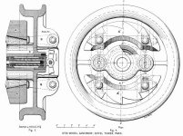 used with the Otis elevators in the Eiffel Tower, an elevation and section
of which are shown in Figs. 3 and 4.
It consists of two toothed weights shown in section at A, A, and in
elevation at A', A', (N, N, on inset Fig. 7). Each of these weights
is fastened to arms of two bell crank B, B, the other arms of Which
are pivoted to the sliding rods C, surrounded by spiral springs D. When
the revolutions of the wheels exceed a certain number per minute, the
weights tend to fly apart under the influence of centrifugal
force, this motion being allowed by the bell cranks and springs as plainly
shown in the figures.
used with the Otis elevators in the Eiffel Tower, an elevation and section
of which are shown in Figs. 3 and 4.
It consists of two toothed weights shown in section at A, A, and in
elevation at A', A', (N, N, on inset Fig. 7). Each of these weights
is fastened to arms of two bell crank B, B, the other arms of Which
are pivoted to the sliding rods C, surrounded by spiral springs D. When
the revolutions of the wheels exceed a certain number per minute, the
weights tend to fly apart under the influence of centrifugal
force, this motion being allowed by the bell cranks and springs as plainly
shown in the figures.
Turning now to the operation of the clutch, Figs.
7 and 8, it will be seen that as the weights N, N, fly
apart their teeth come in contact with the trigger O, fastened to one
end of a rocking shaft to the other end of which is attached a short
arm P, which locks with the nut Q on the rod R, and holds in compression
the spring S. When the teeth of the weights strike the trigger the rocking
shaft makes a partial revolution, lifting the arm P, and releasing the
spring S. This expands and presses the rod R against the long arm of
the bell crank I. This pressure is transmitted to the mechanism of the
clutch, causing it to operate in the manner already described. The whole
mechanism is very ingenious and all tests, both in the shops and on
the cars, have shown its operation to be effective. It would seem, however,
as if the construction lay open to the charge of unnecessary complexity.
The fewer parts such a mechanism has and the simpler these parts are
put together the better, generally speaking.
The contractors for the construction and equipment
of the road proper were given in our issue of Aug. 18. The contractors
for the engines and hoisting machinery were the Walker Mfg. Co., of
Cleveland, O., to whom we are indebted for the drawings of that machinery
shown on the inset. The safety clutches were manufactured by Otis Bros.
& Co., of New York City.
|